
In this example we will do a simple flashing led project for a stm32f0discovery board, I used Coocox IDE 1.7.8. I did try the newer version and didn’t really like the way you selected a chip and imported components via the repository.
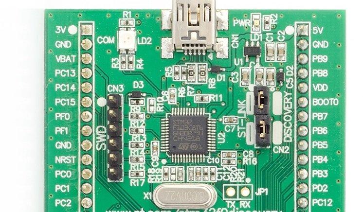
This example will involve connecting a common anode RGB led to the stm32f0discovery and then we will flash the red, green and blue individually. Here is a picture of the board, we will connect the following
command anode – 3v.
RED – PC0
GREEN – PC1
BLUE – PC2
Here is a typical RGB led module that I use in many simple beginner projects, I find it easier than messing about with breadboards.
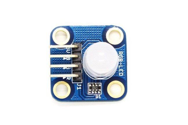
rgb led module
Code
As stated I used Coocox for this, I will be trying various compilers such as MDK and IARs offerings eventually.In this example I pulled in the RCC, GPIO, CMSIS boot and MO CMSIS core. You can see this in the screenshot below
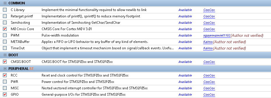
coocox repository
There are a few comments in the code, I’ll go through some of this in more detail in a later tutorial
[codesyntax lang=”cpp”]
/**
/*
 * @Project: RGB Led example
 * @Microntroller: STM32F030R8T6
 */

#include <stdint.h>
#include <system_stm32f0xx.h>
#include <stm32f0xx_gpio.h>
#include <stm32f0xx_rcc.h>


int main(void)
{
	GPIO_InitTypeDef InitGpio;
	unsigned int i = 0;

	// Initialises the system clock
	SystemInit();

	// Enables the clock for GPIOC
	RCC_AHBPeriphClockCmd(RCC_AHBPeriph_GPIOC, ENABLE);

	// Configures the GPIOC pin8 and pin9, since leds are connected
	// to PC8 and PC9 of GPIOC
	InitGpio.GPIO_Pin = (GPIO_Pin_0 | GPIO_Pin_1 | GPIO_Pin_2);
	InitGpio.GPIO_Mode = GPIO_Mode_OUT;
	InitGpio.GPIO_Speed = GPIO_Speed_Level_1;
	InitGpio.GPIO_OType = GPIO_OType_PP;
	InitGpio.GPIO_PuPd = GPIO_PuPd_NOPULL;

	// Initialises the GPIOC
	GPIO_Init(GPIOC, &InitGpio);
	GPIO_SetBits(GPIOC, 0xFF); //common anode led - so outputs high
    while(1)
    {
    	// Turn ON the Red Led
    	GPIO_ResetBits(GPIOC, (GPIO_Pin_0));
    	// Delay
    	for (i = 0; i < 0x0FFFFF; i++);
    	// Turn OFF the Led
    	GPIO_SetBits(GPIOC, (GPIO_Pin_0));
    	// Delay
    	for (i = 0; i < 0x0FFFFF; i++);

    	// Turn ON the Green Led
    	GPIO_ResetBits(GPIOC, (GPIO_Pin_1));
    	// Delay
    	for (i = 0; i < 0x0FFFFF; i++);
    	// Turn OFF the Led
    	GPIO_SetBits(GPIOC, (GPIO_Pin_1));
    	// Delay
    	for (i = 0; i < 0x0FFFFF; i++);

    	// Turn ON the Blue Led
    	GPIO_ResetBits(GPIOC, (GPIO_Pin_2));
    	// Delay
    	for (i = 0; i < 0x0FFFFF; i++);
    	// Turn OFF the Led
    	GPIO_SetBits(GPIOC, (GPIO_Pin_2));
    	// Delay
    	for (i = 0; i < 0x0FFFFF; i++);
    }
}
[/codesyntax]
With a bit of luck you will see your RGB led cycling through the three main colours
