
This proved to more problematic – see the code section
The MLX90614 is a non-contact infrared thermometer with a measurement range from -70 to +380 degree Celsius. Just connect the four leads to your Wemos and you will have a accurate thermometer with a resolution of 0.01 and a accuracy of 0.5 degrees, or for that matter you can use any microcontroller that can communicate with it through it’s I2C interface.
Being an I2C device you simply need to connect to the SDA, SCL and choose a suitable GND and Vin. I used 3.3v to be safe, although the breakout states 3 to 5v.
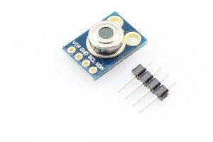
This version I chose comes with a breakout board with all of the components needed for operation. Here is a picture of that breakout board
Features:
Small size, low cost
Mounted on a breakout board with two types of pins
10k Pull up resistors for the I2C interface with optional solder jumpers
Factory calibrated in wide temperature range:
-40 … + 125 ° C for sensor temperature and
-70 … + 380 ° C for object temperature.
High accuracy of 0.5 ° C over wide temperaturerange (0 … + 50 ° C for both Ta and To) High (medical) accuracy calibration
Measurement resolution of 0.02 ° C
Single and dual zone versions
SMBus compatible digital interface
Customizable PWM output for continuous reading
Sleep mode for reduced power consumption
Connection
VIN -> Arduino Due 3.3v
GND -> Arduino Due GND
SCL -> Arduino Due 21
SDA -> Arduino Due 22
Code
This is an interesting one as the Adafruit and other libraries I tested did not work, the readings were far too high – 1038. Digging on some forums I found this which seems to return better values. I’ll see if I can find a reason why various libraries return poor readings, the code in these libraries does look fairly basic
[codesyntax lang=”cpp”]
#include <Arduino.h>
#include <include/twi.h>

#define ADDR      0x5A

//EEPROM 32x16
#define TO_MAX    0x00
#define TO_MIN    0x01
#define PWM_CTRL  0x02

//RAM 32x16
#define RAW_IR_1  0x04
#define RAW_IR_2  0x05
#define TA        0x06
#define TOBJ_1    0x07
#define TOBJ_2    0x08

#define SYNC_PIN  2

static const uint32_t TWI_CLOCK = 100000;
static const uint32_t RECV_TIMEOUT = 100000;
static const uint32_t XMIT_TIMEOUT = 100000;

Twi *pTwi = WIRE_INTERFACE;

static void Wire_Init(void) {
  pmc_enable_periph_clk(WIRE_INTERFACE_ID);
  PIO_Configure(
  g_APinDescription[PIN_WIRE_SDA].pPort,
  g_APinDescription[PIN_WIRE_SDA].ulPinType,
  g_APinDescription[PIN_WIRE_SDA].ulPin,
  g_APinDescription[PIN_WIRE_SDA].ulPinConfiguration);
  PIO_Configure(
  g_APinDescription[PIN_WIRE_SCL].pPort,
  g_APinDescription[PIN_WIRE_SCL].ulPinType,
  g_APinDescription[PIN_WIRE_SCL].ulPin,
  g_APinDescription[PIN_WIRE_SCL].ulPinConfiguration);

  NVIC_DisableIRQ(TWI1_IRQn);
  NVIC_ClearPendingIRQ(TWI1_IRQn);
  NVIC_SetPriority(TWI1_IRQn, 0);
  NVIC_EnableIRQ(TWI1_IRQn);
}

static void Wire1_Init(void) {
    pmc_enable_periph_clk(WIRE1_INTERFACE_ID);
  PIO_Configure(
      g_APinDescription[PIN_WIRE1_SDA].pPort,
      g_APinDescription[PIN_WIRE1_SDA].ulPinType,
      g_APinDescription[PIN_WIRE1_SDA].ulPin,
      g_APinDescription[PIN_WIRE1_SDA].ulPinConfiguration);
  PIO_Configure(
      g_APinDescription[PIN_WIRE1_SCL].pPort,
      g_APinDescription[PIN_WIRE1_SCL].ulPinType,
      g_APinDescription[PIN_WIRE1_SCL].ulPin,
      g_APinDescription[PIN_WIRE1_SCL].ulPinConfiguration);

  NVIC_DisableIRQ(TWI0_IRQn);
  NVIC_ClearPendingIRQ(TWI0_IRQn);
  NVIC_SetPriority(TWI0_IRQn, 0);
  NVIC_EnableIRQ(TWI0_IRQn);
}

void setup() {
  Serial.begin(9600);

  pinMode(SYNC_PIN, OUTPUT);
  digitalWrite(SYNC_PIN, LOW);

  Wire_Init();
  // Disable PDC channel
  pTwi->TWI_PTCR = UART_PTCR_RXTDIS | UART_PTCR_TXTDIS;
  TWI_ConfigureMaster(pTwi, TWI_CLOCK, VARIANT_MCK);
}

void loop() {
  uint16_t tempUK;
  float tempK;
  uint8_t hB, lB, pec;

  digitalWrite(SYNC_PIN, HIGH);
  delayMicroseconds(10);
  digitalWrite(SYNC_PIN, LOW);

  TWI_StartRead(pTwi, ADDR, TOBJ_1, 1);

  lB = readByte();
  hB = readByte();

  //last read
  TWI_SendSTOPCondition(pTwi);
  pec = readByte();

  while (!TWI_TransferComplete(pTwi))
    ;
  //TWI_WaitTransferComplete(pTwi, RECV_TIMEOUT);

  tempUK = (hB << 8) | lB;
  if(tempUK & (1 << 16))
  {
    Serial.print("Error !");
    Serial.println(tempK);
  }
  else
  {
    tempK = ((float)tempUK * 2) / 100 ;
    //Serial.print("Temp UK: ");
    //Serial.print(tempUK);
    Serial.print(" C: ");
    Serial.println(tempK - 273.15);
  }
  //Serial.print(hB, HEX);
  //Serial.print(" : ");
  //Serial.print(lB, HEX);
  //Serial.print(" : ");
  //Serial.println(pec, HEX);

  delay(2000);
}

uint8_t readByte() {
  //TWI_WaitByteReceived(pTwi, RECV_TIMEOUT);
  while (!TWI_ByteReceived(pTwi))
    ;
  return TWI_ReadByte(pTwi);
}

static inline bool TWI_WaitTransferComplete(Twi *_twi, uint32_t _timeout) {
  while (!TWI_TransferComplete(_twi)) {
    if (TWI_FailedAcknowledge(_twi))
      return false;
    if (--_timeout == 0)
      return false;
  }
  return true;
}

static inline bool TWI_WaitByteReceived(Twi *_twi, uint32_t _timeout) {
  while (!TWI_ByteReceived(_twi)) {
    if (TWI_FailedAcknowledge(_twi))
      return false;
    if (--_timeout == 0)
      return false;
  }
  return true;
}

static inline bool TWI_FailedAcknowledge(Twi *pTwi) {
  return pTwi->TWI_SR & TWI_SR_NACK;
}
[/codesyntax]
Links
Here is a link to the datasheet and also a breakout
